Use case diagram is considered as part of the Unified Modeling Language that is used to analyze and define the system. It is utilized to model the functionality of a system using actors and use cases. A use case diagram simply portrays actions or activities by the people and the system outside the system.
Basic Symbols in use case diagram:
System – You can illustrate the scope and boundaries of the system through a rectangular shape which contains use cases and outside of the system’s boundaries are the actors that will be part of the system.
Use case – use cases are represented by an oval shape. Inside the oval are labels that begin with a verb that will stand for the system’s functions. It is a collection of sequence of actions a system performs that produces a reliable and easy to understand result of value to a particular actor. A use case is a normal interaction between a user or the actors and the computer system and a simple documentation of the behavior of the system. It is useful to capture system requirements and for validation.
Actors – the actors are the users of the system. It signifies a role that someone may play and it could be any person, organization, or a system that interacts with application but is external to it.
Relationships – from the word itself, relationship determines the connection between an actor and a use case with a simple line. A line with an arrow head that points from one actor to another actor simple define an actor is an inheritance of the pointed actor. With the connection among use cases, which is a line with an arrow head that points from one use case to another is labeled with “<> or <>” and “<>”. A “<>” relationship indicates that a certain use case is needed by the other use case to be able to perform a certain task. Another relationship is “<>” which specifies an alternative options which is under a certain use case.
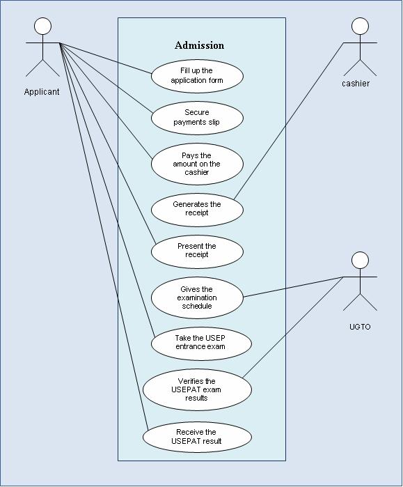
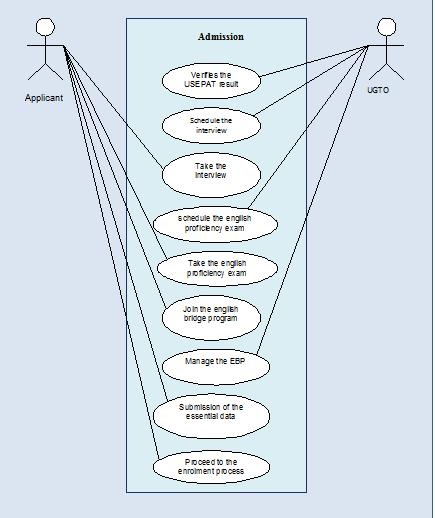
The pre-enrolment system caters the admission of the applicant to the University. This includes the USEPAT, interview, English Proficiency Exam and the English Bridging Program. Below are the two use case diagrams that illustrate the flow of the pre-enrolment system through its actors and the use cases. The first diagram shows the procedure from taking the application form to acquiring the USEPAT result. The following diagram is simply the continuation of the first use case diagram that illustrates the interview and bridging processes.
Basic Symbols in use case diagram:
System – You can illustrate the scope and boundaries of the system through a rectangular shape which contains use cases and outside of the system’s boundaries are the actors that will be part of the system.
Use case – use cases are represented by an oval shape. Inside the oval are labels that begin with a verb that will stand for the system’s functions. It is a collection of sequence of actions a system performs that produces a reliable and easy to understand result of value to a particular actor. A use case is a normal interaction between a user or the actors and the computer system and a simple documentation of the behavior of the system. It is useful to capture system requirements and for validation.
Actors – the actors are the users of the system. It signifies a role that someone may play and it could be any person, organization, or a system that interacts with application but is external to it.
Relationships – from the word itself, relationship determines the connection between an actor and a use case with a simple line. A line with an arrow head that points from one actor to another actor simple define an actor is an inheritance of the pointed actor. With the connection among use cases, which is a line with an arrow head that points from one use case to another is labeled with “<
USEP’s pre-enrolment system
The pre-enrolment system caters the admission of the applicant to the University. This includes the USEPAT, interview, English Proficiency Exam and the English Bridging Program. Below are the two use case diagrams that illustrate the flow of the pre-enrolment system through its actors and the use cases. The first diagram shows the procedure from taking the application form to acquiring the USEPAT result. The following diagram is simply the continuation of the first use case diagram that illustrates the interview and bridging processes.


 Posted by


